SNHRRT
Method for spectral normal hemispherical reflectance measurement (spectral normal absorptivity / emissivity) in visible and infrared spectral range at room temperature.
The basic parts of the experimental setup are a spectrofotometer, an integrating sphere accessory and a calibrated reflectance standard. The method enables to analyze both transparent and opaque bulk materials and coatings deposited on substrates at room temperature and in the spectral range of 0.32 – 20 um.


MEASUREMENT SYSTEM
Components of the measurement system:
UV-VIS-NIR spectral range
- Dispersive spectrofotometer Specord 210 Plus
- Integrating sphere accessory with angle of incidence of 8°
- Zenith Polymer standards with different degree of reflectance, specular reflectance standards with high and low reflectance
MIR spectral range
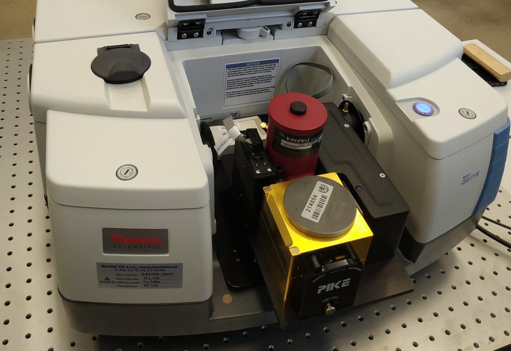
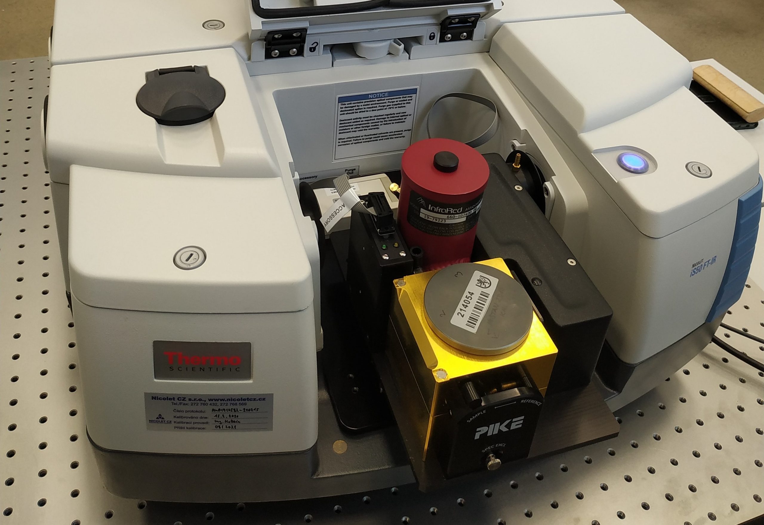
- Nicolet iS50 FTIR spectrometer
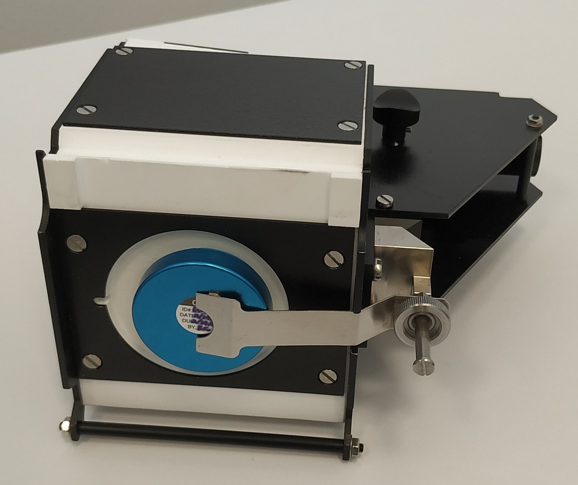
- Integrating sphere accessory with angle of incidence of 12°
- Molybdenum reflectance standard
Description of the measurement system
UV-VIS-NIR spectral range
Radiation from the internal source of the spectrofotometer is directed by a mirror into the reflectance measurement accessory – integrating sphere, where it hits the sample (or reflectance standard) located at the opposite side of the sphere. The radiation incident on the sample is reflected into the integrating sphere. The inner surface of the integrating sphere is made of highly-reflective Spectralon material, which ensures reflection (scattering) of the incident radiation in all directions, i.e. to the entire hemisphere. Radiation reflected from the sample surface is repeatedly reflected inside the integrating sphere until it leaks through the detector port onto the detector.
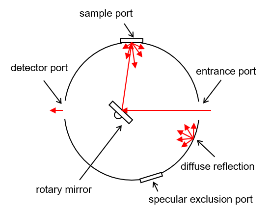
MIR spectral range
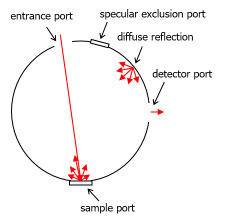
Radiation from the internal source of the spectrometer enters the reflectance measurement accessory – integrating sphere and a rotary mirror directs it to the analyzed sample (or reflectance standard). The radiation incident on the sample is reflected into the integrating sphere. The inner surface of the integrating sphere is made of a highly-reflective gold coating, which ensures reflection (scattering) of the incident radiation in all directions, i.e. to the entire hemisphere. Radiation reflected from the sample surface is repeatedly reflected inside the integrating sphere until it leaks through the detector port onto the detector. The advantage of the integrating sphere is the collection of radiation reflected into all directions, which allows determination of the absolute value of the reflectance for a general sample (any surface roughness).
aRRANGEMENTS OPTIONS
UV-VIS-NIR spectral range
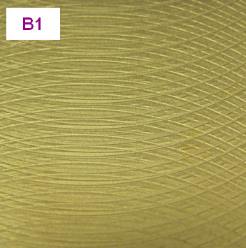
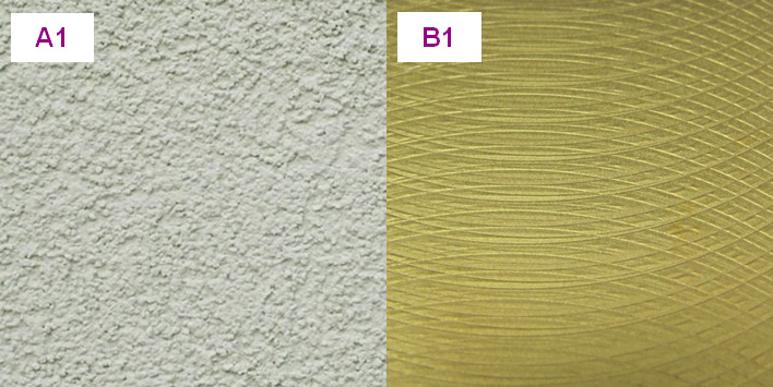
| V1 | Basic configuration without additional adapter and shielding element Sample type A1, B1, C1, D1 |
MIR spectral range
| V1 | Basic arrangement without additional adapter and shielding element Sample type A1, A2 |
| V2 | Arrangement with shielding element and without additional adapter Sample type B1, B2 |
| V3 | Arrangement with additional adapter and without shielding element Sample type C1, C2 |
| V4 | Arrangement with additional adapter and shielding element Sample type D1, D2 |
SpecifiCATION
Wavelength range
UV-VIS-NIR spectral range
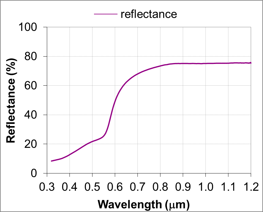
| V1 | 0.32 – 1.2 μm |
MIR spectral range
| V1 | 1.5 – 20 μm |
| V2 | 1.5 – 20 μm |
| V3 | 1.5 – 15 μm |
| V4 | 1.5 – 15 μm |
Measured quantities
UV-VIS-NIR spectral range
- Spectral normal hemispherical reflectance relative
- Proportion of specular and diffuse components of reflectance
MIR spectral range
- Spectral normal hemispherical reflectance relative
- Proportion of specular and diffuse components of reflectance
Computed quantities
UV-VIS-NIR spectral range
- Spectral normal hemispherical reflectance absolute
- Band normal hemispherical reflectance
- Solar normal hemispherical reflectance
- Spectral normal absorptivity
- Band normal absorptivity
- Solar normal absorptivity
- Spectral hemispherical absorptivity
- Band hemispherical absorptivity
- Solar hemispherical absorptivity
MIR spectral range
- Spectral normal hemispherical reflectance absolute
- Band normal hemispherical reflectance
- Integrated normal hemispherical reflectance
- Spectral normal emissivity
- Band normal emissivity
- Total normal emissivity
- Spectral hemispherical emissivity
- Band hemispherical emissivity
- Total hemispherical emissivity
- Spectral normal absorptivity
- Band normal absorptivity
- Integrated normal absorptivity
- Spectral hemispherical absorptivity
- Band hemispherical absorptivity
- Integrated hemispherical absorptivity
samples
Analyzed materials
According to the nature of the surface

According to the material
- Opaque coating on a bulk substrate
- Semitransparent coatings on semitransparent or opaque bulk substrate (measured is emissivity of coating – substrate system)
- Bulk ceramics
- Metals
- Plastics
- Glass
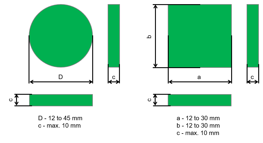
Dimensions and shapes of samples
UV-VIS-NIR spectral range
- Samples in a form of a block with one side (measured side) having a planar surface with diameter of 12 – 45 mm or a planar surface with edge of 12 – 30 mm
- Maximum sample height 10 mm
- Maximum sample weight 1 kg
MIR spectral range
- Samples in a form of a block with one side (measured side) having a planar surface with diameter of at least 22 mm
- Maximum dimensions of measured side correspond to a square with a side length of 80 mm
- Height of the block – not limited
- Maximum sample weight 1 kg

results
Method output
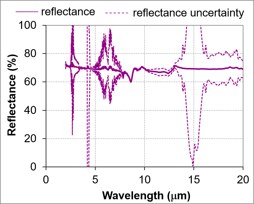
- Spectral analyzed quantity – graphical display of spectral quantity distribution (separately for each measurement) and data in electronic form
- MIR spectral range – the spectrum is influenced by atmospheric absorption (higher uncertainty) in the bands of 2.5 – 2.95 um, 4.17 – 4.5 um, 4.8 –7.9 um and 13.2 – 17.2 um
Form of the results
Basic
- Measurement protocol in electronic form in PDF format or in printed form – UV-VIS-NIR example, MIR example
- XLSX file that contains a measurement protocol in electronic form and values of the analyze variable (for MIR range including the measurement uncertainty)
Extended
- Technical report in electronic form in PDF format or in printed form; the report contains description of method and measurement procedure, measured samples, summary of results of all measurements, discussion of the results and conclusions of the research