EDEHT
Method for effective directional emissivity measurement as a function of temperature, ie. the sample emissivity valid for the defined measurement system.
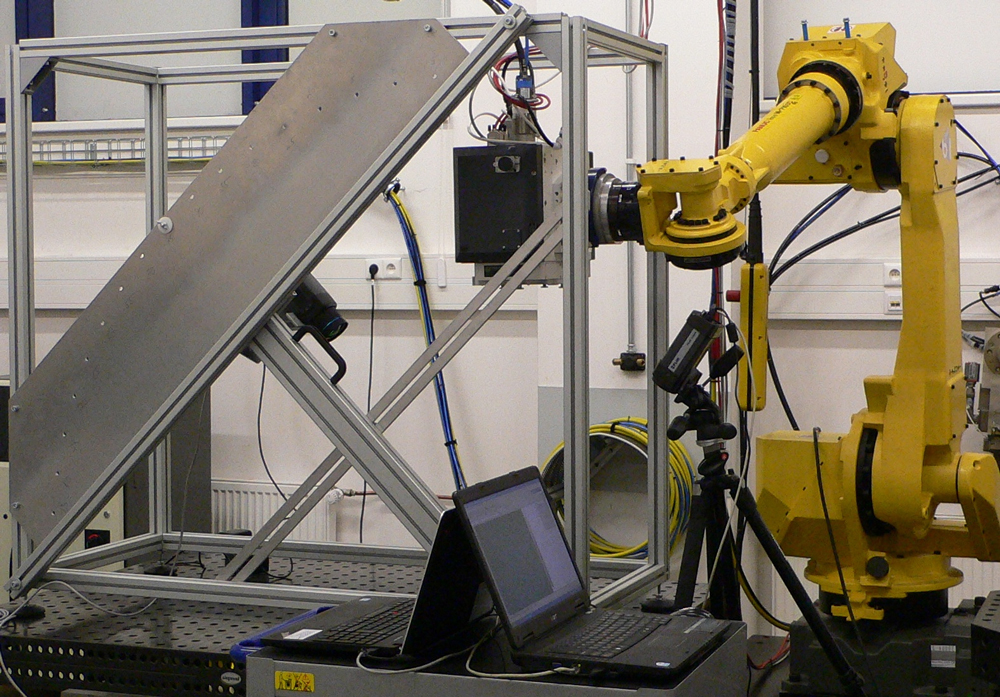
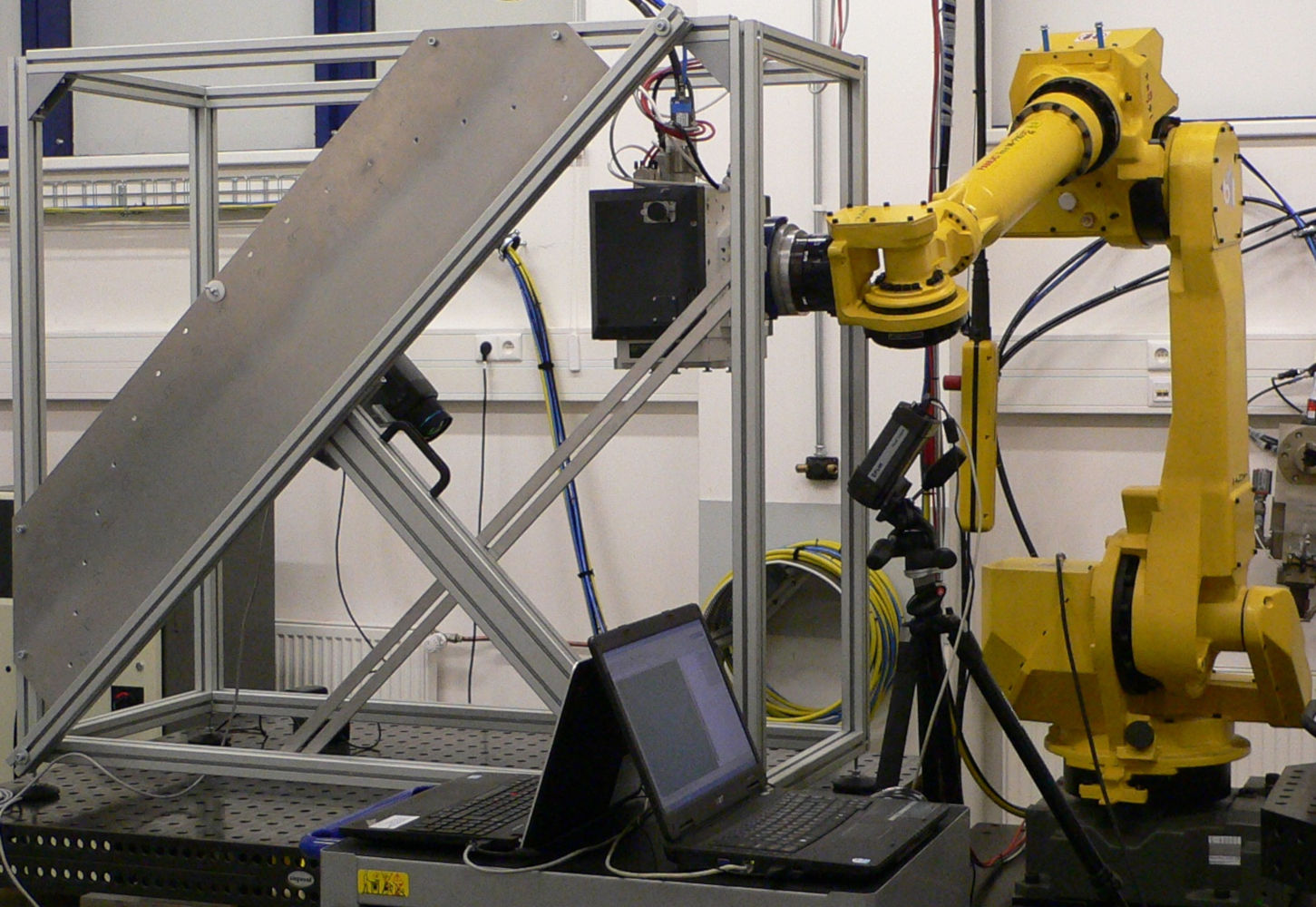
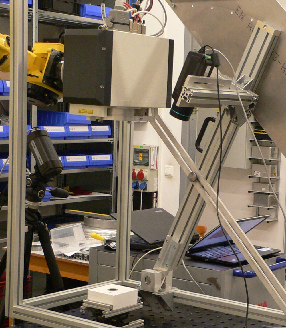
The basic parts of the experimental setup of the method are a system for sample heating, a system for contact and non-contact measurement of sample surface temperature, a metal construction with movable arm and infradetector – infrared camera or pyrometer. The method enables to analyze both bulk materials and coatings deposited on bulk substrates at an angle of 5° – 85° to the normal of sample surface. The samples can be measured in the temperature range of 100°C – 1000°C. The wavelength range is defined by the infradetector (standard 7.5 – 14 um).


METHOD USE
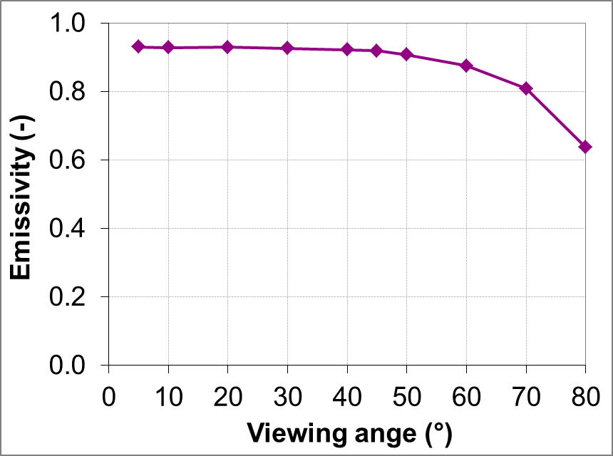
The effective directional emissivity is sample emissivity for particular device (infrared camera/pyrometer) and radiation angle to the normal of sample surface. Each measurement instrument is characterized by the different spectral sensitivity. Therefore, the sample emissivity may vary in a specific wavelength band for each measurement instrument. Furthermore, the emissivity is also changing differently for various materials with the viewing angle. The changes are seen at angles greater than 20° from normal to the sample surface, significant changes are evident at angles greater than 60°. Therefore, the correct emissivity for the viewing angle and measurement device (effective directional emissivity) is important for the correct surface temperature measurement.
EDEHT measurement method is based on the temperature field scanning of the sample by using the infrared camera at a selected angle from the normal to the surface, everything depending on the temperature. If sample surface temperature is known, the effective emissivity for the selected infrared camera and viewing angle can be evaluated by the method of known temperature.
MEASUREMENT SYSTEM
Standard components of the measurement system
| sample heating system | titanium heating plate and temperature controller (low temperature applications), 5kW laser system with scanning head (high temperature applications) |
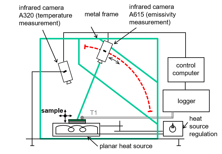
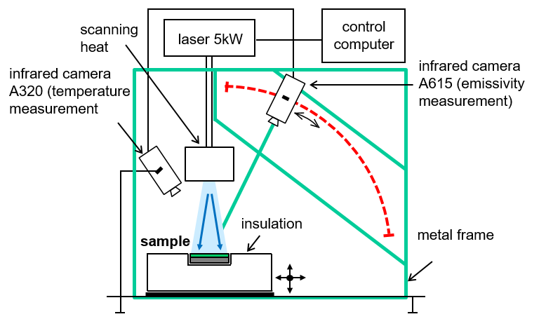
| system for sample surface temperature measurement | FLIR A320 infrared camera (thermocouple measurement system) |
| detection system | FLIR A615 infrared camera |
| Opto-mechanical components | metal construction with movable arm, linear micro-positioners |
Description of the measurement system
Low temperature applications: A planar heat source (e.g. titanium heating plate) is used for sample heating on its surface is placed the measured sample. The required sample temperature is achieved by controlling the heat source power. Sample surface temperature is measured by two methods. The first method uses the infrared camera FLIR A320 and a reference coating with a known effective emissivity coated on one half of each sample. The sample radiation is detected at an angle of 10° to the normal of sample surface. The second method is based on a contact temperature measurement by a thermocouple welded to the surface of each sample.
High temperature applications: The measured sample is placed in a holder made of ceramic fiber insulation, which is mounted on an optical table so that it is possible to precisely position it by linear translation stages. Heating of the sample is realized by the high power laser system with a scanning head. The sample temperature is achieved by controlling the laser power. The required homogeneous temperature field of the sample is achieved by an appropriate choice of time-space laser beam movement across the front side of the sample. The sample surface temperature is measured by the infrared camera FLIR A320 and a reference coating with a known effective emissivity coated on one half of each sample. The viewing angle of the camera is 20° to the normal of sample surface.
In both cases, the sample radiation is detected by the infrared camera FLIR A615, which is mounted on a movable arm of metal frame. The arm enables to adjust the infrared camera position in the defined angles to the normal of sample surface in the range from 5° to 85° with the step of 5°. In addition to the FLIR A615, it is possible to use other infrared cameras and pyrometers from our technical equipment or non-contact temperature sensors supplied by the customer.
Specification
Detection systems
| System | Wavelength band | Temperature range |
|---|---|---|
| Standard | ||
| FLIR A615 infrared camera | 7.5 μm – 14 μm | -40°C – 2000°C |
| Special | ||
| FLIR A320 infrared camera | 7.5 μm – 13 μm | -20°C – 1200°C |
| Optris PI 400 infrared camera | 7.5 μm – 13 μm | -20°C – 1500°C |
| Micro-Epsilon ThermoIMAGER TIM 160 infrared camera | 7.5 μm – 13 μm | -20°C – 900°C |
| LumaSense MIKRON MCS640 infrared camera | 780 nm – 1080 nm | 800 – 3000°C |
| FLIR SC7650 infrared camera | 3 μm – 5 μm | 5°C – 300°C |
| Pyrometers and infrared cameras supplied by a customer |
Wavelength range
- Depending on the detection system, default in the wavelength bands of 7.5 – 14 μm
Temperature range
- 100 – 1000 °C depending on the detection system and measured sample (shape, size)
- 100°C – 350°C for low temperature applications
- 300° – 1000°C for high temperature applications
Viewing angle range
- 5° – 85° with step of 5°
Measured quantity
- Effective directional emissivity
samples
Analyzed materials
- Opaque coatings (thickness of tens to hundreds of micrometers) on a bulk substrate
- Semitransparent coatings (thickness of tens to hundreds of micrometers) on an opaque bulk substrate (measured is emissivity of coating – substrate system)
- Bulk ceramics
- Metals
Rozměry a tvary vzorků
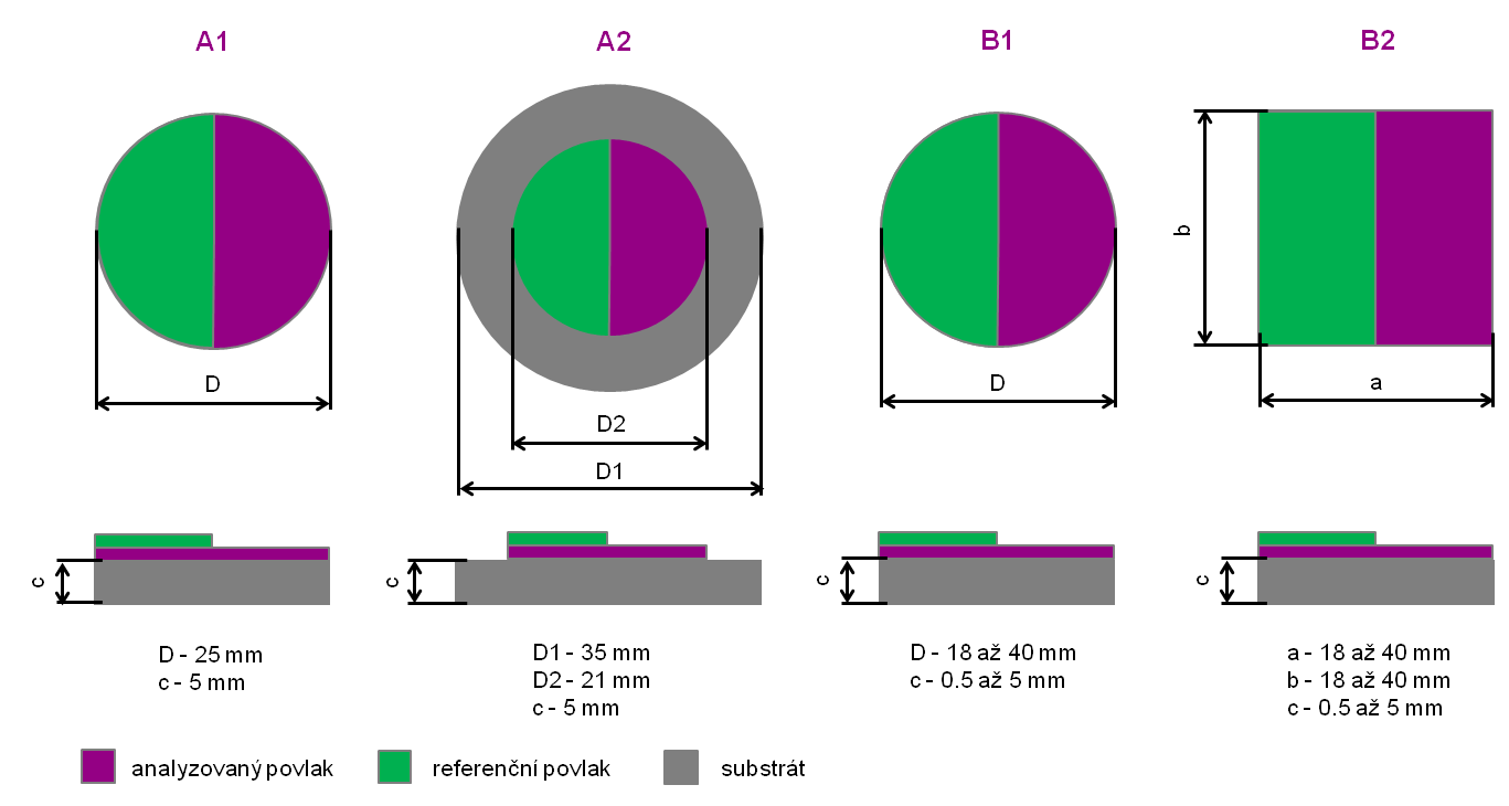
Standard samples
| A1 | circular samples with a diameter of 25 mm and a thickness of 5 mm (low temperature applications) |
| A2 | circular samples with a diameter of 35 mm and a thickness of 5 mm (bulk materials, substrates) + coating with a diameter of 21 mm in the middle of the sample (high temperature applications) Standard substrates – refractory steel CSN 41 7153, blasted on the front side |
Non-standard samples
Only low temperature applications
| B1 | circular samples with a diameter of 18 – 40 mm and a thickness of 0.5 – 5 mm |
| B2 | square samples with an edge size of 18 – 40 mm and a thickness of 0.5 – 5 mm |
Additional requirements for samples
- Analysed bulk materials and substrates must not transmit radiation with a wavelength of 1030 nm and must withstand the required thermal load
- Maximum roughness of the part of the sample, on which will be applied the reference coating is Ra = 5 um, Rz = 35 um
- All samples should have a planar surface
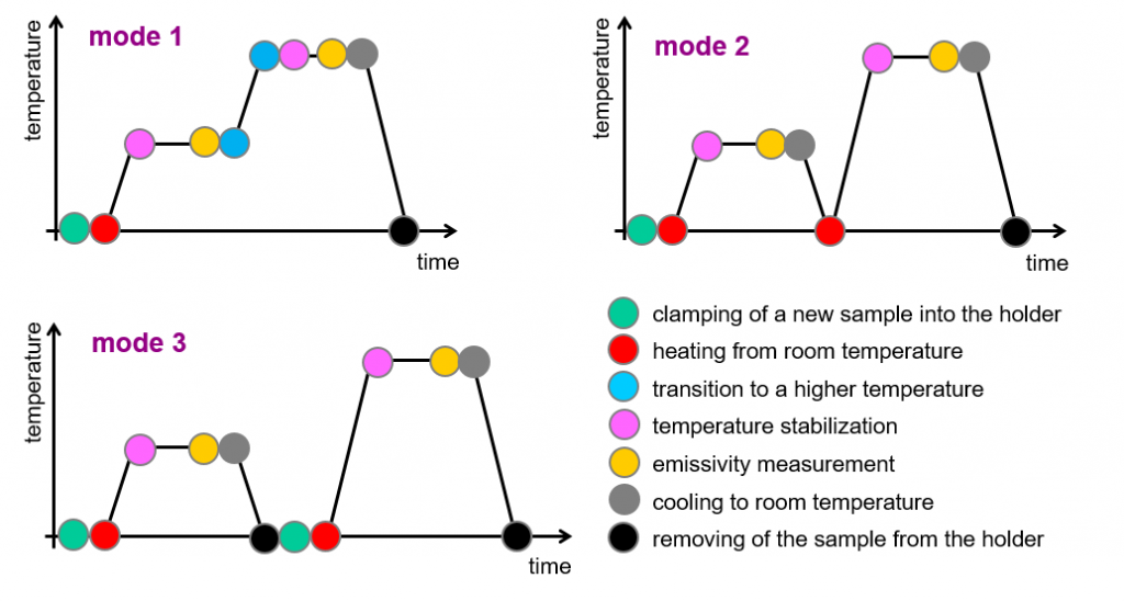
temperature modes
Time-temperature measurement modes
| mode 1 | Step heating of one sample – increasing of the temperature from 300°C to 1000°C with a temperature step of 100°C (50°C) |
| mode 2 | Heating of one sample with temperature cycling – cooling to room temperature before raising the temperature to the next temperature level |
| mode 3 | Heating of new sample at each temperature level – a new sample is heated from room temperature directly to the next temperature level |
| mode 4 | Individual time and temperature mode – on demand defined sequence of time and temperature steps of sample heating and emissivity measurement |
results
Method output
- Effective directional emissivity – graphical display of directional emissivity distribution (separately for each measurement) and data in electronic form
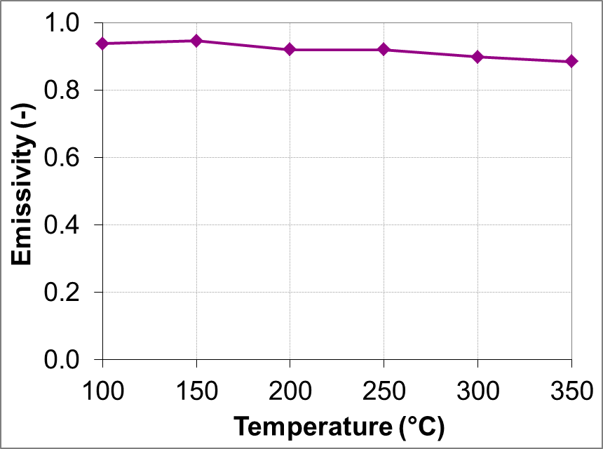
- Temperature dependence of effective directional emissivity – graphical display of temperature dependence of effective emissivity (separately for each viewing angle) and data in electronic form
Form of the results
Basic
- Measurement protocol in electronic form in PDF format or in printed form – example
- XLSX file that contains a measurement protocol in electronic form and emissivity values
- XLSX file that contains a summary of emissivity values in electronic form
Extended
- Technical report in electronic form in PDF format or in printed form; the report contains description of method and measurement procedure, measured samples, summary of results of all measurements, discussion of the results and conclusions of the research